Outline Link to heading
- Project Summary
- Design
- Testing and Results
- CAD Drawings
- Conclusion
- Recommendation for Future Work
- References
- Appendix
Project Summary Link to heading
Recently, there has been a growing interest in the development and utilization of renewable energy sources such as wind energy. The idea behind this is that harnessing this clean and abundant resource can help fight against climate change and overuse of fossil fuels. With this in mind, our group of 6 students from the E26 class at UC Berkeley was tasked to design, fabricate, and test a wind turbine system using computer-aided design (CAD) techniques and 3D printing. Our primary objectives were to design and fabricate the turbine rotor blades, the support tower, and the generator housing, as well as determine the power output and stiffness of our wind turbine tower.
During the journey of this project, we put an emphasis on growing our knowledge of CAD and 3D printing technology, which allowed us to manufacture a lightweight and efficient wind turbine. From the turbine rotor blades to the support tower with the motor housing using 3D printing techniques, as a team we designed and fabricated each piece. This allowed our team to build rapid prototyping skills, test the product, and optimize our design to ensure that it met our performance goals.
After completing our wind turbine weighing only 276.2 grams, with a tower height of 15 inches and a blade-to-fan distance of 22 inches, it was tested under a wind speed of 25.2 mph. We measured the performance of our wind turbine by determining the power output and the stiffness of the wind tower. The turbine achieved a peak power output of 1315 watts with a blade speed of 4587 rpm, a current of 435.5 Amps, and a voltage of 2.80 volts. The stiffness of the tower was tested under a maximum load of 4000 Kg, resulting in a deflection of 2.87 mm. These strong results proved that our goals and objectives we worked to meet were met.
From high team collaboration through regular meetings to discuss improvements to our design and update to the team camaraderie and love for learning we shared, our team was able to leave feeling successful, brighter, and more well versed in the details of researching, CADing, 3D printing, and testing of a product. Our turbine not only met, but exceeded the initial objectives set forward, creating a very efficient, lightweight, and sturdy wind turbine. It is time we use work like this to further spread the notion that we need to continue studying and developing renewable energy sources.
Introduction Link to heading
The wind turbine industry is one of the leading technologies in renewable energy. Following a simple principle, the turbines transform kinetic energy from the wind into electrical energy; in 2022, about 10.2% of total U.S. utility-scale electricity was solely generated by wind turbines.
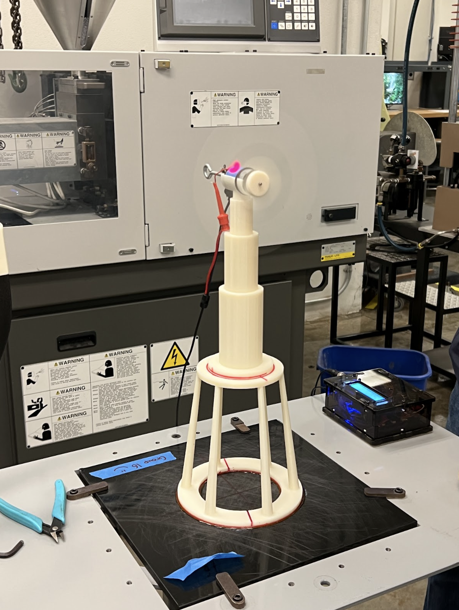
For our final project, we were tasked to model and build a horizontal-axis wind turbine. We first constructed and three-dimensionally modeled our tower components using CAD Solidworks. Once completed, the parts were 3D printed and glued together. Finally, the wind turbine was brought to the lab, where it was tested for its power produced and stiffness.
Our team began creating our design by first researching the two main components of the wind turbine: the blade and the tower. The maximum allowed length of the blade was 3 inches, and the maximum allowed height of the tower was 16 in; the entire volume of the wind turbine tower (not including the blade) had to be within 17 in3. Beginning with the blade profile, our team researched the most popular blade profiles, angles of attack, twist angle, and optimal blade count to ensure that our turbine would be able to produce the maximum amount of energy possible. Each member drafted a sketch for the blade design and compiled their research together; we followed a similar process for the tower design, where each member individually researched into existing wind turbine designs and sketched multiple tower designs to showcase to the group.
 Figure 1: The following images represent the members’ individual blade profile designs.
Once everyone had completed their individual designs, we discussed and finalized a design that incorporated what we believed to have the best features (out of the ideas shared). Our final wind turbine design consisted of a relatively lighter, yet still stable structure that allows wind to flow easily towards and around the tower, mitigating its risk of collapsing.
 Figure 2: The following images represent the members’ individual tower designs.
After drafting the sketch for our final design, we constructed both the blade, tower, and rotor design digitally using Solidworks. Due to the limitations of the 3D printer, we had to construct the tower in two parts; before sending in the files for printing, we assembled the parts digitally to ensure that our model would cohesively fit together.
Once the model was printed, the parts were glued and assembled. Our team then returned to the lab the following week, where we tested the power generated, RPM, and stiffness of the tower. Overall, we found our wind turbine to perform better than we had expected.
 Figure 3: The following image on the left shows our turbine model assembled together.
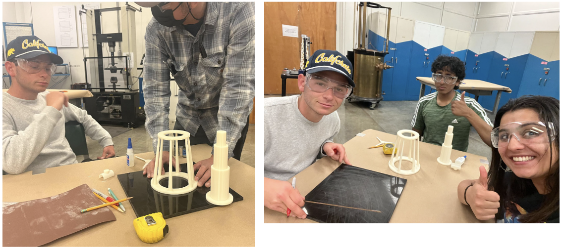 Figures 3.1 and 3.2: The following images show the gluing process.
Theory Link to heading
In this project, we used an equation* to calculate the theoretical maximum power of the wind turbine for the purpose of comparing our results from the wind turbine testing to the theoretical value. We define the following variable for the equation. *A journal from the University of South Florida provides the equation for calculating the theoretical maximum power.
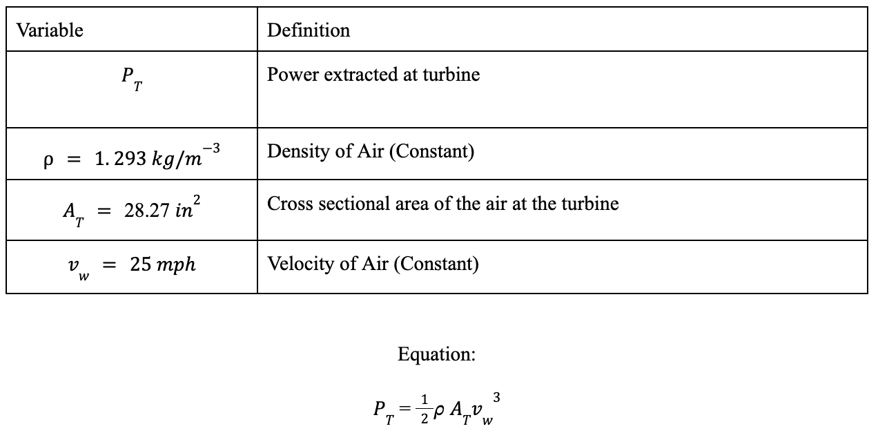
Plugging in the values, we achieve the following theoretical power value of 15.24 Watts for our windmill. We will compare this value to the actual power value later on in this report to calculate the efficiency of the wind turbine.
Design Link to heading
During our design process, we used hand-drawn pictures for a rough draft of both our blade and tower. Then we used Solidworks as our major tool to create a model from the sketch. Below are the sketches and designs of the blades and tower.
Blade Design Link to heading
Our rotor blade design was based on NACA 4412; the angle of attack is 4 degrees and angle of twist is 17 degrees. Our design consists of 3 blades. We chose to model our blade after the NACA 4412 because with our research, we determined that this profile is the most commonly used when designing blade designs and generates the most power. Our research also included going through experimental data on trusted websites that displayed which number of blades (Fig. 4), angle of attack (Fig. 5), and angle of twist (Fig. 6) was the most optimal for generating the most power.
 Figure 4: The coefficient of performance vs. number of blades
 Figure 5: Glide ratio vs. Angle of Attack
 Figure 6: Rotor ratio vs. Twist Angle
 Figure 7: Sketch of the profile of the blade
 Figure 8: Windmill tri-blade portion
Tower Design Link to heading
Our tower has three parts: the base, the tower, and the motor. We took the design of Figure 9A to use as the base of the tower because we believed the stool-shaped structure would well support the stress of the entire tower. We chose Figure 9B as the tower because cylinders have significant structural integrity and it also contributes to making the tower look unique.
 Figure 9: Sketches of the base and tower of the windmill designs with a front, topical, and side view
 Figure 10: CAD Designs of the Base, Tower, and Motor Holder
Finite Element Analysis (FEA) Simulation Link to heading
Using the FEA simulation provided by Solidworks, we determined the deflection (stiffness) of the wind turbine tower. First, we create a new study in Solidworks with the assembly of the tower open. Before we started the simulation, we set the material of the entire assembly to acrylic, fixed the bottom plane of the tower base as the fixed geometry, and applied 9.81 N of force on the face of the motor for the external load. Below are the plots of displacement, stress, and safety factor.
 Figure 11: Stress Plot
 Figure 12: Displacement Plot
 Figure 13: Factor of Safety
For the load vs. deflection equation, we loaded 4 unique amounts of force using the same procedure described above with the FEA simulation. Then, the data was entered into a Google Spreadsheet to calculate the equation of load vs. deflection.
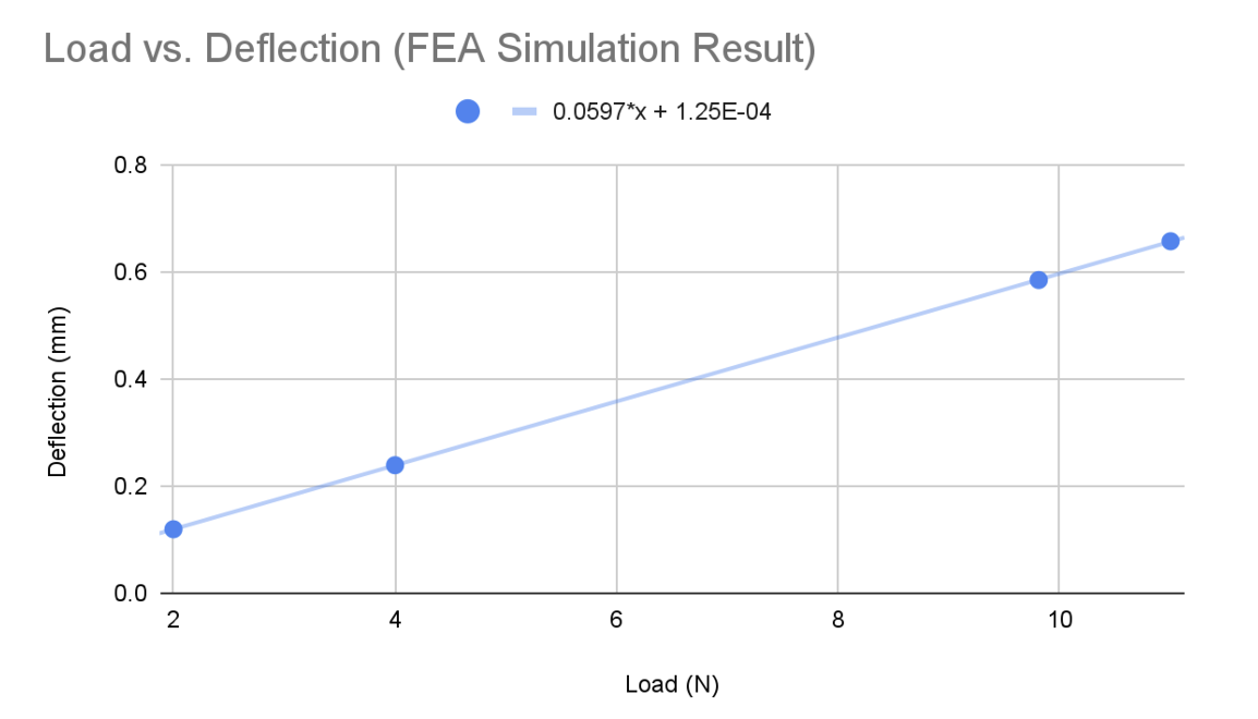
Setting D as deflection (mm) and L as load (N), we can simply the equation of load vs. deflection produced by FEA simulations as shown below: D = 0.06L + 0.000125
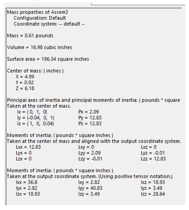
Mass Properties of the Entire Tower:
Testing and Results Link to heading
Testing Process: Power Link to heading
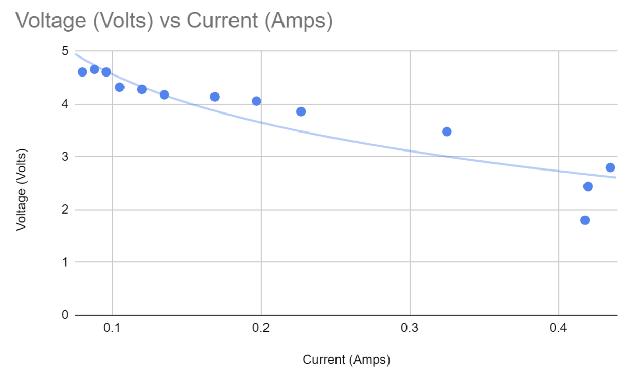
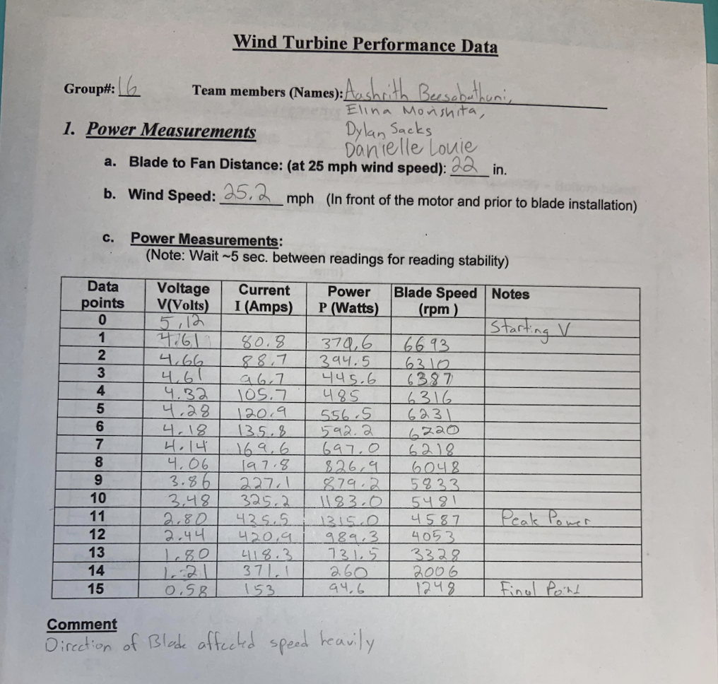
Testing Process (Power): The testing progress conducted on 5/2 consisted of 2 main tests. The 2 points of data that would best measure our turbine’s performance are total power and stiffness. To begin with, out group started with the power test, whose main components were the Load Box (Fig. 14) and the Electrical Meter. The Load Box (pictured below) consists of a generator, and also a display which shows stats such as the power (mW), current (mA), and the Voltage of the Turbine. The goal of these tests was to adjust the potentiometer to achieve the highest possible power (mW), based on the load conditions of the wind being blown at the turbine. Data such as voltage, current, and power was collected from the display on the load box. Another important piece of information was the RPM of the turbine, which was measured through a Tachometer (Fig. 15).
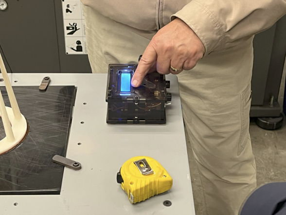 Figure 14: Load Box during power experiment
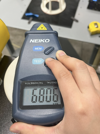 Figure 15: Tachometer
The main steps are as follows:
- Secure turbine to testing through clips on side
- Turn on the blower and measure wind velocity through the use of an Anemometer (Fig. 16) to reach around 25 mph
- Measure distance from turbine to blower and record (Fig. 17)
- Connect motor from turbine to Load Box through power positive and negative terminals (Fig. 18)
- Turn potentiometers counter clockwise and turn blower on
- Turn up resistance at small intervals and record data points until peak power is found.
- After, record extra data points to show power trailing down after the peak display.
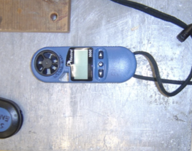 Figure 16: Anemometer
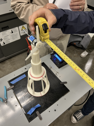 Figure 17: Distance from Blower to Turbine
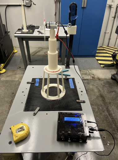 Figure 18: Connecting Motor to Load Box
Testing Process: Stiffness Link to heading
The test we conducted after the power test is the Stiffness Test. This test was meant to show the strength of the base of our tower, by continuously adding force to the plate that houses the motor. Through the use of a pulley system attached to an eye bolt on our turbine, we were able to continuously add hooked weights (Fig. 19) to see the deflection caused by different weight values. To accurately measure this, a dial indicator (Fig. 20) was placed behind the tower’s motor plate, and zeroed to the point where there was no load on the eyebolt. As the weight on the pulleys was gradually increased during testing, we collected measurements from the dial indicator to show how much the top of our turbine moved, or how much it deflected.
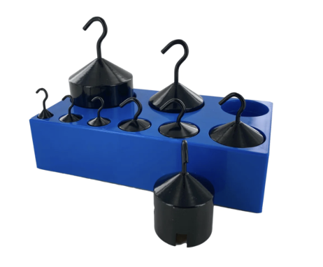 Figure 19: Assortment of hooked gram weights
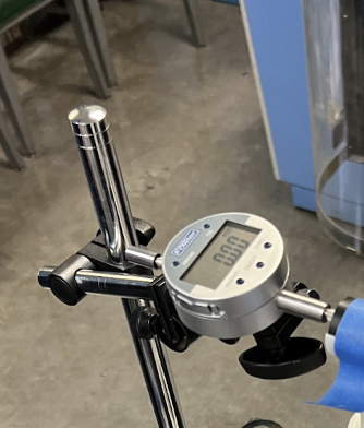 Figure 20: Dial Indicator
The main steps are as follows:
- Clamp down the wind turbine bottom plate into test apparatus (Figure 21)
- Attach pulley system string to eyebolt at the motor housing
- Set up Dial Indicator behind tower, and zero at initial position (Figure 22)
- Add weights in increments of 100 g, and measure deflection at each point
- (Optional) Continue going till failure, adding weights of higher increment (Figure 23)
- Record and Analyze data to calculate stiffness.
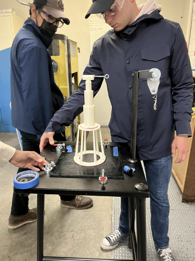 Figure 21: Clamping down Turbine
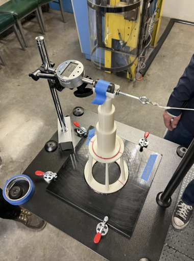 Figure 22: Zeroed dial indicator position
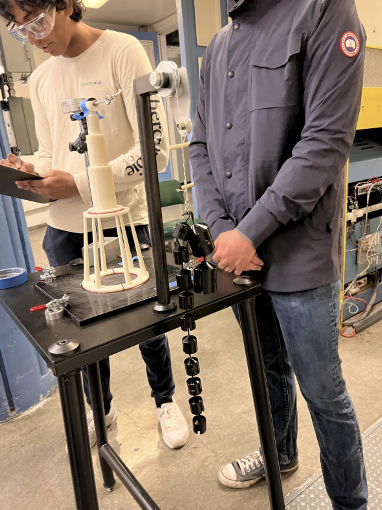 Figure 23: Adding more weights to test max deflection
Data Tables Link to heading
Data Table 1
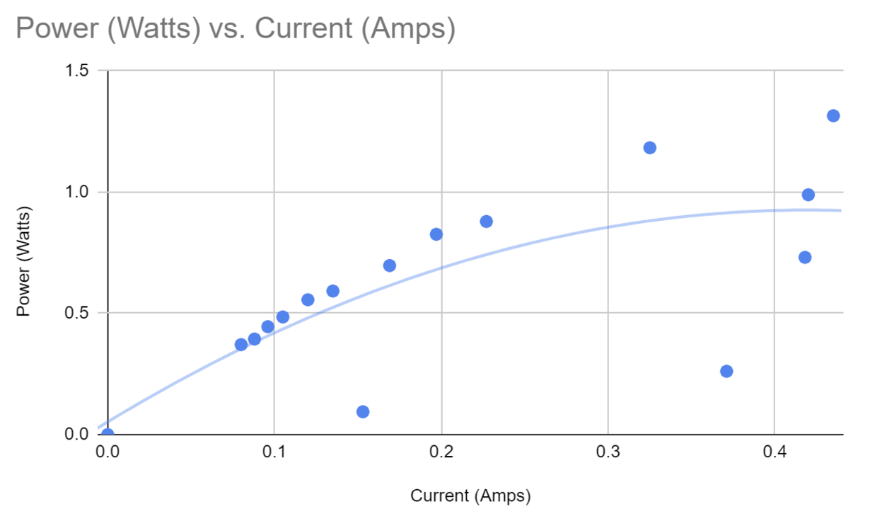
| Voltage (Volts) | Current (Amps) | Power (Watts) | Blade Speed (RPM) |
|---|---|---|---|
| 5.12 | 0 | 0 | 0 |
| 4.61 | 0.08 | 0.371 | 6693 |
| 4.66 | 0.088 | 0.394 | 6310 |
| 4.61 | 0.096 | 0.445 | 6387 |
| 4.32 | 0.105 | 0.485 | 6316 |
| 4.28 | 0.12 | 0.556 | 6231 |
| 4.18 | 0.135 | 0.592 | 6220 |
| 4.14 | 0.169 | 0.697 | 6218 |
| 4.06 | 0.197 | 0.826 | 6048 |
| 3.86 | 0.227 | 0.879 | 5833 |
| 3.48 | 0.325 | 1.183 | 5481 |
| 2.8 | 0.435 | 1.315 | 4587 |
| 2.44 | 0.42 | 0.989 | 4053 |
| 1.8 | 0.418 | 0.731 | 3328 |
| 1.21 | 0.371 | 0.261 | 2006 |
| 0.58 | 0.153 | 0.094 | 1248 |
Data Table 2
| Load (kg) | Load (N) | Deflection (mm) |
|---|---|---|
| 0.1 | 0.98 | 0.1 |
| 0.2 | 1.96 | 0.19 |
| 0.3 | 2.94 | 0.27 |
| 0.4 | 3.92 | 0.37 |
| 0.5 | 4.9 | 0.45 |
| 0.6 | 5.88 | 0.52 |
| 0.7 | 6.86 | 0.6 |
| 0.8 | 7.84 | 0.69 |
| 0.9 | 8.82 | 0.78 |
| 1 | 9.8 | 0.84 |
| 1.5 | 14.7 | 1.27 |
| 2 | 19.6 | 1.65 |
| 3 | 29.4 | 2.32 |
| 4 | 39.2 | 2.87 |
Plots Link to heading
Efficiency Link to heading
The theoretical max power of the turbine was calculated to be 15.24 watts from the Theory Section of the Report. With our max power being 1.315 watts, this shows an efficiency of 8.62%. In reference, most modern wind turbines have an efficiency of around 40%.
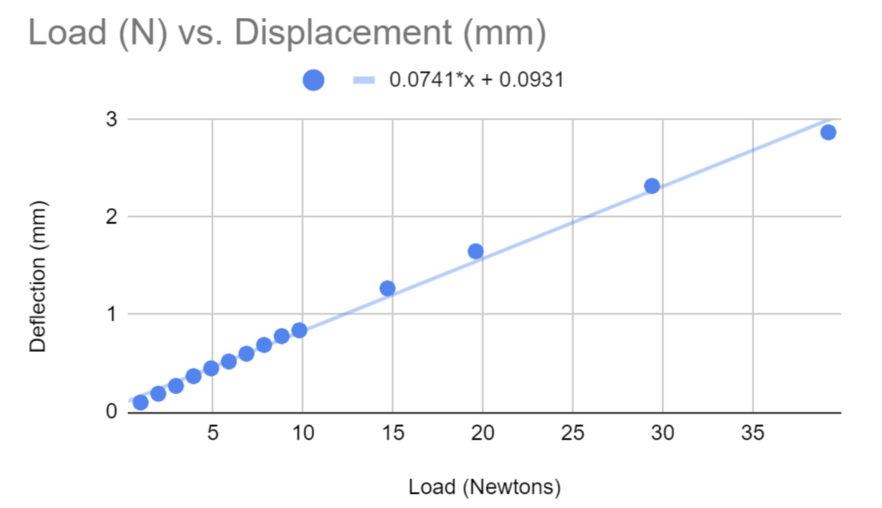 Here, the slope of the line is shown to be around 0.0741, which is the Stiffness (N/mm) of the turbine.
CAD Drawings Link to heading
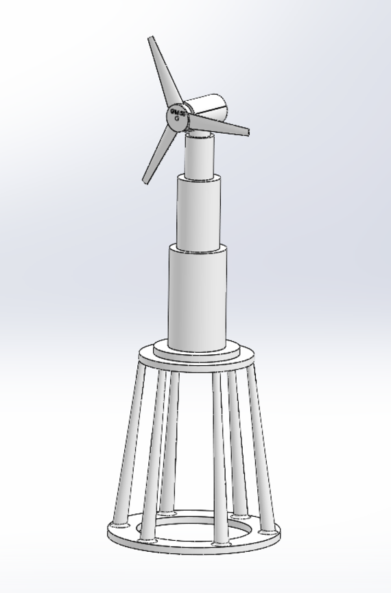
3D Assembly Drawing of the Wind Turbine Link to heading
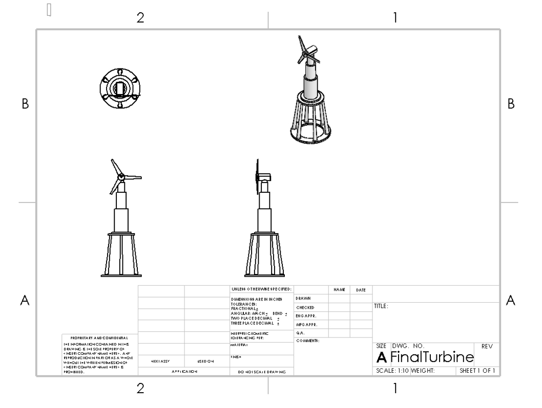 Figure 24: 3D Assembly Drawing of the Wind Turbine
Exploded View of the Tower Link to heading
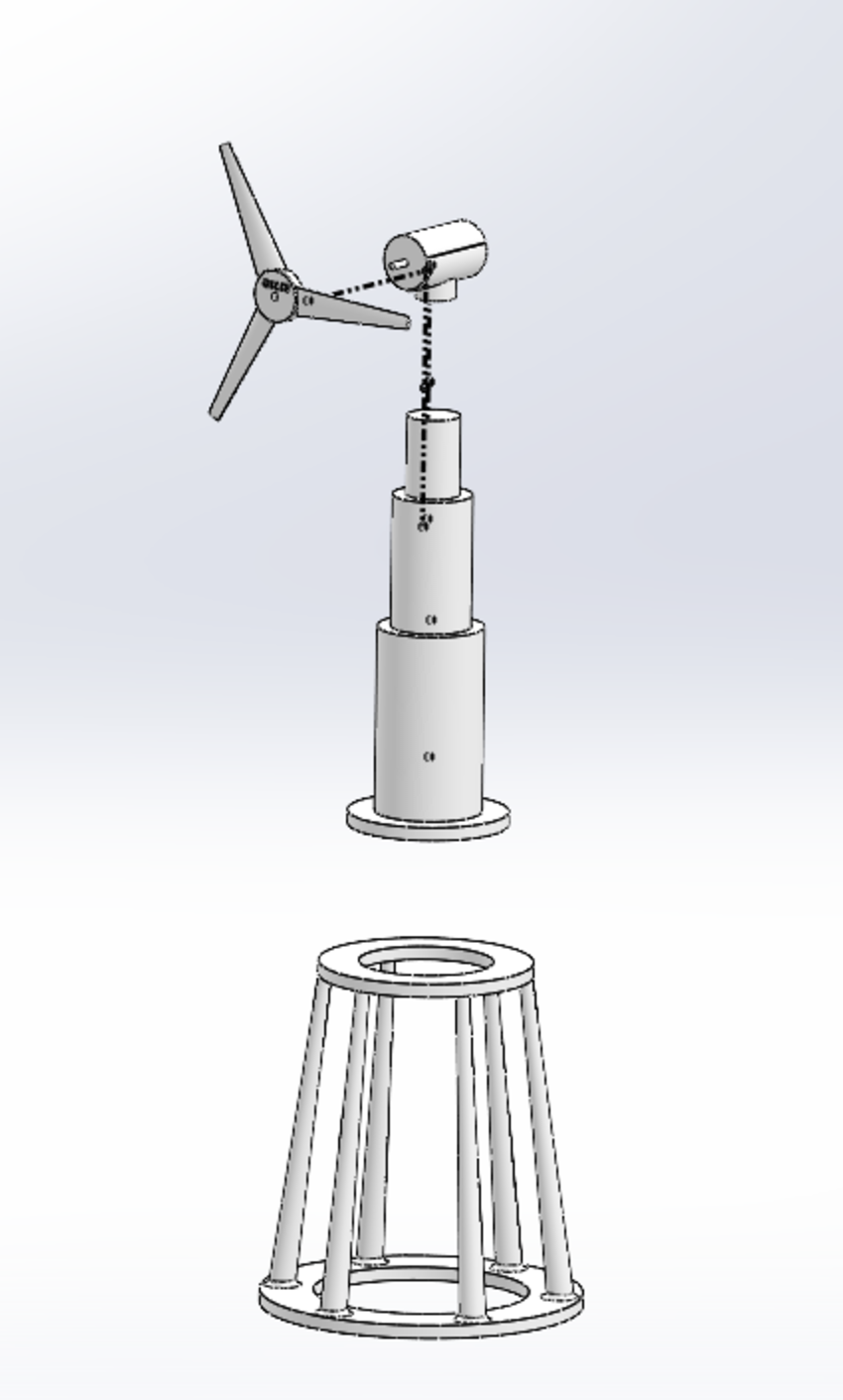 Figure 25: Exploded View of the Tower
2D Drawing of the Tower with Overall Dimensions Link to heading
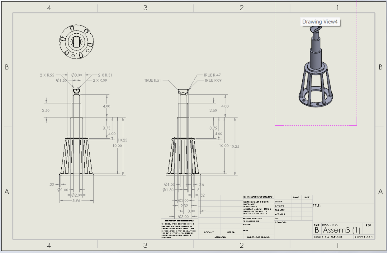 Figure 26: 2D Drawing of the Tower with Overall Dimensions
Conclusion Link to heading
Our project involved a few key components: designing, CADing, fabricating, 3D printing, and testing. During these phases, our objectives were to design and fabricate the turbine rotor blades, the support tower, and the generator housing, as well as determine the power output and stiffness of our wind turbine tower. With each of these aspects in mind, our project successfully achieved these objectives, creating a highly efficient wind turbine.
Through rapid prototyping, testing, and optimization of our design we expanded our knowledge of CAD and 3D printing techniques. Furthermore, we were able to carry out these initiatives meeting regularly to discuss improvements and collaborate to consistently find the best approach to reach the success we found.
Discussing the data, our wind turbine weighing only 276.2 grams, with a tower height of 15 inches and a blade-to-fan distance of 22 inches, performed extremely well during testing with a wind speed of 25.2 mph. Our turbine achieved a peak power output of 1315 watts with a blade speed of 4587 rpm, a current of 435.5 Amps, and a voltage of 2.80 volts. Furthermore, the stiffness of the tower was tested under a maximum load of 4000 Kg, creating a deflection of 2.87 mm.
The power of the turbine at 100% efficiency was 15.24 watts which when compared to the maximum power of 1.315 watts is an 8.62% efficiency. The efficiency of our turbine was clearly not the strongest and definitely could do a lot more work. In comparison to modern wind turbines today, they have an efficiency rate of at least 40% with much higher wattage being yielded.
Our tower not only met the goals set by both ourselves and the class, but also exceeded them. Through our efficient and durable design, we were able to prove how adaptations to a wind turbine’s height, weight, angles, and more can produce different outcomes. Using our project’s success, we hope to continue to emphasize the importance of wind turbines in helping to produce more renewable energy and fight against climate change.
Recommendations for Future Work Link to heading
If given the opportunity to revise upon our aforementioned design, there are a few structural and design changes that our team would definitely be interested in making. The first would be thickening the wall of the motor housing. As you can see in Figure 27, the housing of the motor was so thin. Fortunately, inserting the motor did not break or bend the housing as we inserted the motor with care. However, the image depicts its slenderness, which could lead to fragility and breakage of the housing when the motor was inserted. Additionally, if greater forces were exerted on the motor - perhaps for more extreme tests or if the windmill was used in the real world, it is possible that the motor housing would no longer be functional and could easily break just due to the thinness of the motor housing.
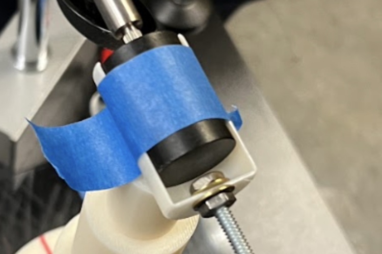 Figure 27: Image of the motor housing with the motor inside
Another change we may have made would be altering the design such that the base was more simple. What we noticed in our design was that although both the parts of the base were quite rudimentary in design, they both were quite different from each other. It would have been more interesting to try to align the platforms more to make both parts more similar to one another. This would be especially useful when gluing as we noticed that even when the concentric circular portions of the platforms were aligned, the amount of surface area that actually overlapped between the two was not as significant. This misalignment could have led to more significant problems, and would definitely be something we would have liked to improve upon in the future if given more leniency for the maximum mass threshold.
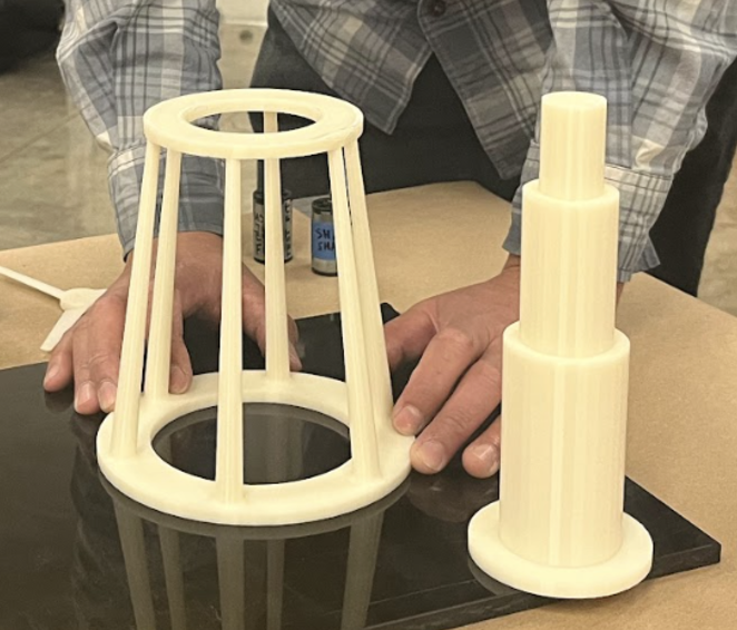 Figure 28: Image of the two base parts, depicting the size differences between the portions that were glued and the lesser overlapping surface area than the team had anticipated.
Additionally, our efficiency yield for this wind turbine was 15.24 watts at an efficiency of 100%. When comparing this with our maximum power of 1.315 watts, our efficiency rate was 8.62%, which is a significantly low value, especially when compared to modern-day wind turbines that yield over 40% efficiency at least. Due to this reason, one future work that we could add to further augment our efficiency would be to research the difference in designs between ours and these heavy-duty turbines to see if there is a way we can alter the shape of our blades to increase the efficiency. Some ways we could potentially do so is to adjust the blade shape to make it sharper in some portions, thicker towards the centers and thinner towards the outer edges of the blade, and perhaps even experiment with having more or fewer blades as well to see if that could alter efficiency yields.
Lastly, an interesting design reconfiguration that the team would have enjoyed designing and perhaps implementing instead would be using a criss-crossed lattice-styled design for the base of the tower to ensure greater sturdiness and to allow the base to sustain much greater weights. Included in Figure 29 are a few lateral designs of the lattice-styled architecture that could have been incorporated for the topology of our windmill. Unfortunately, due to mass restrictions and time constraints, we weren’t able to engineer such a complicated design as a team. Given more flexibility, our team would be greatly interested in developing numerous lattice structures to explore the differences between the triangular lattice, quadrilateral lattice, and even the differences between the different criss-crossed patterns as a whole within such structures.
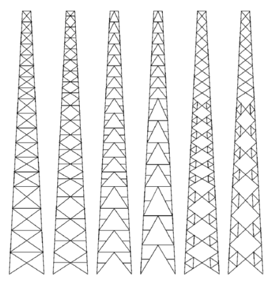 Figure 29: Image of different lateral lattice structure designs.
Based on perhaps testing those different lateral lattice structures, it would be interesting to take it a step further and try different lattice tower structures for their architectural design and gluing steps as well. For example, as seen in Figure 30, there are different base formats we could use such as a hybrid shaped lattice tower or a pyramidal shape lattice tower. Not only can we modify the lateral lattice structures, but we can also modify the unification of all the sides to create a sturdier and more complex base structure to modify the wind turbine as a whole.
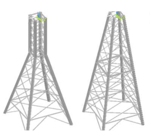 Figure 30: Two different lattice architectural structures
Left: Hybrid shaped lattice tower structure
Right: Pyramidal shaped lattice tower structure
References Link to heading
- Adeyeye1, K. A., Ijumba1, N., & Colton1, J. (2021, June 1). IOPscience. IOP Conference Series: Earth and Environmental Science. Retrieved May 5, 2023, from https://iopscience.iop.org/article/10.1088/1755-1315/801/1/012020
- A comparative criteria method for telecommunications towers with different topological designs - Scientific Figure on ResearchGate. Available from: https://www.researchgate.net/figure/Lattice-towers-with-different-topological-designs_fig1_267840973 [accessed 6 May, 2023]
- CFD investigation on the aerodynamic characteristics of a small-sized … (n.d.). Retrieved May 6, 2023, from https://www.researchgate.net/publication/257774740_CFD_Investigation_on_the_aerodynamic_characteristics_of_a_small-sized_wind_turbine_of_NREL_PHASE_VI_operating_with_a_stall-regulated_method
- Design parameters for NACA 4412 airfoil. parameter design value … (n.d.). Retrieved May 6, 2023, from https://www.researchgate.net/figure/Design-Parameters-for-NACA-4412-airfoil-Parameter-Design-Value_tbl1_318795475
- Maximum efficiency of a wind turbine - University of South Florida. (n.d.). Retrieved May 6, 2023, from https://digitalcommons.usf.edu/cgi/viewcontent.cgi?article=4865&context=ujmm
Appendix Link to heading
Acknowledgements Link to heading
This project was conducted with Dylan Sacks, Elina Morishita, Aashirth Beesabathuni, and Ashna Valia during the 2023 Spring Semester of ENGIN 26 at UC Berkeley through the College of Engineering.